onsdag 3 juni 2015

Arduino to Unity Project Part 6: From zones to direction vectors


In my previous implementation of the Arduino directional input to Unity I divided the scales of the Y and X-axis ranges and gave each zone a number 0-8. This way I only needed to send that number over Serial to Unity. But that also meant that I only could input 8 directions(+ 0 for standing still). After doing some state of the art research I decided that this was not enough. I wanted to be able to input any direction(360 degrees).

To do this we can picture the the analog stick in a coordinate system where the rested position of the thumbstick is in the origo(x1, y1). If I then move the thumbstick in any direction that is going to change the potentiometers value so that I get an x2, y2 position.

v = x2-x1, y2-y1 then then gives me a vector which goes from origo to the new position of the controller. And if I normalize that vector I get a directional vector which is vector of length one that describes a direction. I could then use Unitys tranform.Translate()-function to move an object in that direction in real time, following the user input of X and Y values over the serial port.


Setting up a coordinate system.

First I had to reverse the range of the X-axis from the thumbsticks horizontal potentiometer. For some reason it was made so that the vertical scale was growing upwards but the horizontal scale was growing to the left. To get this to work as a conventional coordinate-system I needed to reverse it so that the X-axis was growing to the right.

For some reason the horizontal scale grows to the left?
Next I calculated the delta X and delta Y. Now the axis range from -510  to  510 with 0 in the middle.

Sending data over serial

Previously I only needed to continuously send number over the serial port to Unity. I could do that with Serial.write() in the Arduino IDE and read it with ReadByte() in Unity. So I was sending one byte with each package. However, 1 byte can only hold a value 0-255. My values where between -510 and 510 and both for the X and Y axis which meant it would no longer fit inside a byte. From reading online it seems possible to send multiple bytes with the Serial.write()-function, however I am not sure how I would receive that without knowing the exact number of bytes sent. I could also try to split the data up into several packages but that would require some algoritm to check when all the parts of a package has been received. Instead I used the Serial.print()-function which prints "Prints data to the serial port as human-readable ASCII text." as it says in the Arduino documentation. I sent the X and the Y value seperated by a "," and then I could use ReadLine() in Unity and then split and parse to get the values. This certainly does not seem like the most elegant method of sending numerical data(converting int to string, converting back to int) but I am yet to find a better way nor anyone else who have done it. Truth is that information on Arduino to Unity Serial communication is quite limited online.

I wrote a C#-script in Unity to read the serial data, split and parse it to X and Y valuebles. Then I created a Vector3(X,0, Y) and normalised it to get a directional vector to describe the direction that I wanted to move the character (in this case the Unity FPScamera). This scrips seemed to work fine. However I had some problems with the serial communication. It seemed that there was a sync problem between the arduino sending code and the unity receiving. My theory is that ReadLine() takes longer than ReadByte() which is why the serial connection are not as direct (write -> read). This causes a async problem. I had to play around with delay(ms) on the Arduino side and ReadTimeout() on the Unity side to make them sync a little bit better. However, if the delays where too high that would gravely affect frame rate in my Unity scene. I finally found out that 4ms delay in arduino and 5ms ReadTimeout() in Unity seemed to work OK. I also had problems with Unity sometimes not parsing correctly and I have a lot of different exceptions when running. I need to optimize the code. But this is the version I have at this point:


It works OK. Framerate is about 60 FPS and acceptable. It is now possible to move in any direction instead of just 8.


Arduino to Unity Project Part 5: State of the art game controller conventions


As of part 4(http://evertlagerberg.blogspot.se/2015/06/arduino-to-unity-project-part-4.html) I have created a 8-directional joystick input from an Arduino to Unity. I have created a script to read the Arduino input over serial in Unity and added that script to control the movement of the FPS Camera.

The next natural step of my project according to the limit-section of my project specification(http://evertlagerberg.blogspot.se/2015/05/arduino-to-unity-project-part-1-project.html) would be to add a second joystick to control camera rotation of the FPS camera in Unity. However, playing around with my 8-directional joystick I started thinking about game controller conventions. How many directions should I be able to move in? Is 8 directions sufficient? This blog is a brief study on game controller conventions.


D-Pad:
The d-pad(short for directional pad) was an early game controller convention, used on home gaming consoles such as the NES, SNES and Playstation among others. The d-pad have four digital buttons which each gives input of one direction (UP, RIGHT, DOWN, LEFT). However in some implementations of the d-pad, the user can get diagonal directions by pressing two buttons. For example pressing both UP and RIGHT would result in a direction input of a diagonal direction between up and and right. Today these are mostly used in 2D-plattform games. The user input in most games a quite straight forward. The user presses the button in the direction he/she wants to move the character and the character moves in that direction.


Joysticks/Arcade sticks:
Joysticks or arcade sticks are a directional controller type that consists of a single stick which gives a digital input depending on its position. Joysticks are available in 2-way, 4-way and 8-way set ups, describing the amount of directions possible to move. Today these are mostly used for fighting games where you want to execute exact button combinations do perform in-game combo attacks.


Dual analog sticks:
Modern home gaming consoles often uses the convention of two dual sticks. The sticks placed on a controller held with both hand and each thumb is resting on one thumbstick. The convention is that the left thumbstick is controlling the character movement and the right thumbstick is controlling the camera rotation. For a first person perspective game this means that the user walks by pressing the left thumbstick in some direction and control the direction the character is turned towards with the right thumbstick. The user input of analog sticks enables user input in any direction (360 degrees) for each stick, meaning that the user can move/rotate in any possible direction. 

This user input requires some training to get accustomed to. Novice user sometimes think it difficult to control these two different movement systems at the same time (plus a dozen other digital buttons usually on these modern controllers). 


Keyboard(WASD) + Mouse:
On PC the controller convention is to control the movement of the player character with the keyboard and rotation of the camera with the mouse. For a first person game this mean the user walks with the help of four digitial buttons on the keyboard (W, A, S, D) and controll the direction the caracter is turning to with the mouse. This is interesting, because the keyboard + mouse controller conventions only have 4 directional input instead of 360 degrees as the dual analog stick. However often the same game are available over a range of platforms where both these conventions are present. I ended thinking about this a lot, until I decided to do a small comparison.


WASD vs Dual analog Comparison:

I tested controlling a first person perspective game first with a WASD + mouse and then with a dual analog stick controller. The "game" I tested with WASD was the Unity FPSCamera. With WASD you can only mouse in four directions. The convention is that you move with the same speed in all directions. Moving sideways by pressing A or S and holding the mouse relatively still makes you move sideways while not turned that way. In real life this movement would be called side-stepping but in games it is called "Strafing". This movement is unnatural since in real life a human can not side-step without decreasing movement speed. In game however, strafing is a common movement convention. However, the the mouse is used to rotate the camera. Moving the mouse forward/backwards results in a motion that in the real world would be moving the head up and down. Moving the mouse left or right represents a motion that by real world terms could be described as turning the whole body in that direction. This means that pressing the digital button W on the keyboard will move the camera forward, however, by turning the mouse to the left/right, changes the rotation of the camera and therefore the direction that is forward. In this way, the WASD + mouse conventions can still move in any possible direction (360 degrees)

The game I tested with a dual analog stick was Bioshock Infinite and I used a Playstation 3 controller.
In comparison to the WASD for movement control, the left thumbstick enables the user to move in any direction(360 degrees). I am not sure if the analog controller input is divided into zones or if it is really completely "any direction", but the user experience is that you can move in any direction. In other words, the control is sensible enough that I can move in a direction of 35 degrees or 45 degrees. However, playing the game I noticed that I am do not give very exact inputs down to a certain direction degree. Rather I tend to move forward and backwards and strafe left and right, occasionally moving diagonally, oftenthe 4 direction convention of the WASD. To do exact movement, instead I use the right stick to turn the direction of "forward", just as I would to with the mouse.  However, the right stick movement is not as quick and exact as using a mouse, so my experience was that I am compensating the slowliness of the right stick, by also using the left stick(more than I would WASD) to adjust movement direction. The combination of the the dual sticks then is a quite complex user input, both controlling the camera movement and the right stick also controlling camera rotation. It is not entirely obvios how to understand the coagency of both thumbs in this set up. I find it very complex and intersting in a way that I have not thought of when previously playing video games.

The camera rotation of the right stick can be made faster/slower depending on how far the analog stick is pushed in a certain direction. If I push the right thumbstick a litte to the right the camera will slowly rotate that way, however If I push it further the the camera rotation will be faster. The user experience is that the change of speed is not in steps but continues. I also noted that the maximum rotation speed UP/DOWN was set to much slower than rotation LEFT/RIGHT in the particular game I tested with(Bioshock Infinite).


Conclusion:
I will use the dual analog stick convention  and try to use the interaction and user expereience from the control of Bioshock infinite to shape my user input.


måndag 1 juni 2015

Arduino to Unity Project Part 4: Thumbsticks 8 directions input to Unity


I used the set up and Arduino sketch I had created for giving input from the thumbstick in form of a number of 0-8 to indicate a direction. I described this here: http://evertlagerberg.blogspot.se/2015/05/ardunion-to-unity-project-part-2.html


I rewrote the Unity C#-script I wrote when I tested with just one button, to act differently on 8 different states(+ 1 state for doing nothing) instead of just on/off that I had for the button. Each number indicates which direction vector is to be used in Unitys tranform.Translate()-function. When we move, we want to move along the x-axis and z-axis but be constant on the y-axis. So the vectors are:


I then added the script to the first person camera:


Arduino to Unity: thumbstick 8-directions from Evert Lagerberg on Vimeo.


Arduino to Unity Project Part 3: Components and soldering


I ordered some new components for my project:

2 x thumbstick joysticks
2 x break out board(for the joysticks)
1 x connecting headers


The thumbstick consist of two potentiometers, one for horizontal movement (X-axis) and one for Vertical(Y-axis). You can also press down on the thumbstick to press a button.

I soldered the thumbstick to the breakout board and then soldered on a 5-pin header to be able to connect cables to the break out board.


Then I connected the thumbstick to the arduino as described here: http://42bots.com/tutorials/arduino-joystick-module-example/


The same link also provided a example sketch to print out the values of the horisontal and vertical potentiometers. The sketch worked fine. I noticed that both potentiometers had a range of 1-1020. For example, pushing the thumbstick all the way forward showed 1020 on the X-axis and 510 on the Y-axis. I wanted to define 8 directions on the thumbstick input so I wrote a sketch that printed a number depending on within which range it was.


The result ended up as this:


söndag 31 maj 2015

Arduino to Unity Project Part 2: Testing, testing


To start off my project I wanted to do a quick and dirty session with the goal to set up a connection between the Arduino IDE and Unity. For this session I had the following equipment:


Hardware:

1 An Arduino Uno microprocessor
2. A Breadboard and Cables
3. a 3-Pin Button
4. a LED-lamp

Software:
1. Arduino IDE
2. Unity 4


Arduino to Serial:

I started by setting up a simple Arduino sketch for using the 3-pin button as a sensor to turn the LED-lamp OFF/ON. I used an example sketch available in the Arduino IDE called Button. There is a tutorial for it here: http://www.arduino.cc/en/Tutorial/Button


 For the wiring a simply used the schematics provided from the retailer where I bought the button:


I also printed the "1" if the button was pressed and "0" if it was open.

This was the result:


Arduino to Unity:

For this part I followed this tutorial: https://www.youtube.com/watch?v=of_oLAvWfSI
I altered the code to write to the serial port. Same as before (1 for button pressed and 0 for button open). I then opened Unity and wrote a C#-script which 

1. Opens a connection to the indicated serialport and reads 1 byte from it.
2. If the byte is 1 the script calls a Translate function and tells it to move to the left. How much it moves depends on the time of the loop. (Everything in both Arduino and Unity-scripts works in a big loop which runs one time per frame).

And then comes the amazing part:
Once you have done the script you just drag it onto  the Unity-asset you want it to control! This might be old news for someone with some experience with Untiy. However, for me this was a very pleasent surprise.

Now I could do this:

Testing Unity Controls

Next I tried to alter the Unity script to do other thing than moving the cube:


Seems to work pretty good!
Now I need more buttons!


onsdag 27 maj 2015

Arduino to Unity Project Part 1: Project Specification

Computer graphics and interaction DH2323
Project Specification:

Alternative input modalities for interaction in Unity

Evert Lagerberg

Background:
Unity is a powerful open source game engine, which comes with many helpful features for creating interaction. For example, to simulate that the player is controlling a character in a first person perspective, we can just drop a camera object into our Unity scene. This gives us the functionality to move the placement of the camera around in the scene with the arrow buttons of the keyboard, and rotate the camera around  the Y and X axis’s with the mouse. But what if we wanted to design how the physical user interacts with the game world. What if we wanted to use other physical sensors or other input modalities to interact with the game world?

Ardouino is a open-source platform which consists of a circuit board with a programmable microprocessors and various sockets for input and output. The inputs can be used to connect sensors to the arduino and the output to connect actuators. Through the Arduino IDE we can program the microprocessor to tell it how to react on sensor input. Arduino allows us to quickly build prototypes for interactive electronic objects.

Problem
Investigate how the Arduino platform can be connected Unity to send input data from the sensors connected to the Arduino. Evaluate the usability(accuracy, satisfaction, stability) of a hardware prototype input system based on a Arduino-to-Unity-connection.

Project plan:
  1. Acquire the necessary hardware components
  2. Solder and connect cables to set up hardware prototype
  3. Investigate how to have the Arduino IDE send input data to Unity, then implement.
  4. Investigate how to connect input data to controls in unity. Then implement.
  5. Investigate how to control objects, cameras in a Unity scene.

Evaluation:
The project will focus on creating a proof of concept prototype of a hardware input system to control objects and camera in Unity. The evaluation of this system will primarily be a technical documentation of how well the connection from Arduino to Unity works. If the prototype works well enough I can do user tests with 1-2 user and interview them about usability.

Limits:
I will start with trying to implement the control of the camera in unity with a thumb stick connected to the arduino (Like an analog stick of a modern game console). The thumb stick can be moved in Y and X axis so this input can be used the camera in for directions. If I have time I will implement a second thumb stick to control rotation of the camera around the Y and  X axises. If I have more time I would like to add other sensors and use them as controls, for example a pressure sensor to act as a button.

Documentation:

I will keep a diary of the progress of the project on my blog: http://evertlagerberg.blogspot.se/

tisdag 3 mars 2015

Information Visualisation Project 3


IVIS Project 3

Demo: http://www.csc.kth.se/~evertla/IVIS15/lab3/


Interpretation of data:


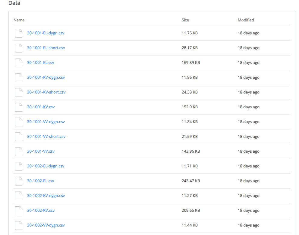
  • 30-1001 = Home 1, 30-1002 = Home 2
  • El/KV/VV = A running measurement tool that at each hour marks the consumed energy(electricity, cold water and hot water) and then resets to zero.
  • El-dygn = Sum of electricity consumed during 24 hours.
  • For each date in data we have two levels of detail(per day and per hour). We don’t always have both of them, sometimes we have neither.

Visual Mappings


The structure and characteristics (and lack of) data does not allow us to use exactly the visual mappings of the Boston Flickr project. However we can interpret the adjectives they have given us and create something that at first glance looks similar to that project but really is quite different. Sometimes in interaction design, you have to be creative in how to persuade clients :) 

Low-fi-prototype: From the Boston Flickr project I kept the circular shape and the use of colors and color intensity. The inner ring represents cold water, the middle ring hot water and the outer ring electricity. The intensity of the color shows high and low periods of consumption. Important!: The color codes where later changed!


It feels natural that cold water should be represented with blue and hot water with red. Electricity cold be yellow or ice blue, but yellow looked ugly and blue was already taken. I chose purple.


Adding live data

I liked their metaphor for a dashboard for a driving car given by the client

I am aware of the problems of rebound effects in persuasive ICT which aims to lower consumption. As argued by Owen (2011) the only effective method of reducing the energy consumption of any system is by the users continuous intent to use less energy. So I wanted to create a visualisation that would inspire the user to always try to lower their energy consumption in comparison with the relevant season of last year. 

High-fi-prototype:

Blue = cold water, Red = hot water, Purple = Electricity
Imagine that we are in looking at the visualisation on Sunday 7 march 2015. The visualisation shows a typical Sunday in March from last year. What this really means is that each hour has been calculated as an average of that hour for every Sunday in march 2014.

On the right side, we see the streaming live data of energy consumption in the home today. (I made a animation that fast forwards so that one hour is about 1 second but the idea is that the visualisation is updated each hour) Live data has been simulated to produce a randomised by believable output on the same color scale as the 2014 data. The user can compare her consumption today with relevant data from last year – in real time! 

By choosing "History" in the menu, she can also access a full visualisation of last year, per month, week or day to analyse her patterns and be more aware of her ecological footprint.